
01 / Data Control
Packet & signaling path
Reliable framed data with CRC-8, ACK/NAK, retries, duplicate protection, source and destination addresses.
Our communicators exchange data and voice through a directional beam of invisible infrared light.
The project keeps data and continuous speech transmissions separate. Proven 38 kHz modules handle addressed messages, acknowledgements, calls and PTT states. A dedicated broadband optical system preserves the analog information needed for intelligible voice.
Reliable framed data with CRC-8, ACK/NAK, retries, duplicate protection, source and destination addresses.
The headset microphone feeds an analog preamp and dedicated voice emitter. A broadband receiver recovers speech for a low-power headphone amplifier.
The packet link starts with an Arduino Nano, a 38 kHz receiver and a 38 kHz transmitter in each handheld. The pin assignments below preserve room for controls, headset audio, status indicators and future fiber.
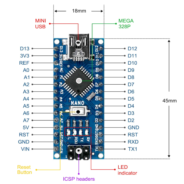
The ATmega328P Nano runs packet framing, CRC checking, acknowledgements, OLED status and later call-control logic. Its compact 5 V platform is the project’s handheld controller.
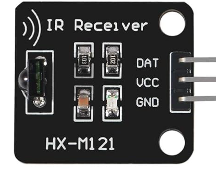
Receives demodulated 38 kHz burst-coded packet and control signals. It is used for text, ACK/NAK, addressing, call state and PTT events—not continuous speech.
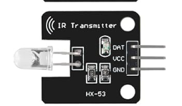
Sends the 38 kHz packet and control channel from the Nano. It carries structured data and signaling; the later continuous-voice path uses a separate higher-power emitter and driver.
Current connections are already used by the packet/OLED baseline. Planned and reserved pins must remain available until their roadmap stage is reached.
Filter the program by phase. Foundations establish the dependable text link. Voice stages develop the headset audio and free-space optical channel. Network stages add selection, repeating and fiber.
The architecture evolves without discarding the reliable subsystems already proven. Arduino Nano boards supervise the operator interface and signaling while dedicated analog electronics handle speech.
The full master roadmaps contain objectives, starting baselines, planned additions, operator examples, verification requirements and success criteria for every stage.
From a single received byte through reliable, OLED-equipped, symmetrical two-way text communication.
Addressing, PTT, private headset voice, optical audio, multi-unit operation, repeaters and fiber.
Every stage introduces one major concept, passes a defined success test, and becomes the known-good baseline for the next.
A 3.5 mm CTIA TRRS headset supplies both microphone and earbuds. The handheld has no onboard microphone or loudspeaker.
Fixed-size buffers, U8x8 OLED text mode and deliberate pin/timer planning respect the ATmega328P’s limited resources.
The IR Optical Communicator is an experimental prototype. These notices describe important limitations and precautions for anyone building, testing or using the system.
Directional infrared communication can reduce unintended signal exposure, but it should not be considered interception-proof or unjammable. Infrared signals may be detected, recorded, reproduced, blocked, or overwhelmed by specialized equipment. This prototype is not intended for emergency, military, medical, or other mission-critical communications.
Infrared light may be invisible to the human eye. High-power infrared emitters can still present an eye-safety hazard even when no visible light is apparent. Use current-limited emitters, suitable diffusers or optics, appropriate operating distances, and applicable photobiological safety guidance. Never look directly into an energized emitter or aim it toward another person’s eyes.